
My simple LED strip controller, Part 2
Apr 25, 2017 · 3 minute readelectronicsMCU
The hardware
To keep it all nice and tidy (and to test another new PCB manufacturer ;) ) the whole project was designed as a small 2-layer PCB in KiCad with some through-hole components for those parts which are either incredibly expensive or hard to source as SMD parts. Of course a decent (even LED) light does require quite a bit of juice so the hardware should be capable of handling 12V and at least 3A with ease.
But one after another:
The power distribution
LED strips come with barrell jacks, PSUs usually come with barrell jacks so it was a complete no-brainer to go with barell jack sockets. Since those are expensive and rather weak (electrically as well as mechanically) as SMD type there really was no other choice than to use through-hole. Only disadvantage is they’re rather large and take a lot of board space due to the huge slots/holes required…
The MCU
Criteria for the MCU:
- Small
- Socketable
- Easy to program
- Trivial to source
- Cheap
- Versatile
My choice here was the ATtiny85 since it it fits the bill quite nicely plus I (and many other poeple) have a lot of experience with it. It can be run with a variety of voltages but for some obscure reason I fail to remember I chose 3.3V. The ATtiny85 also features an internal oscillator dramatically simplifying the setup quite a bit.
The voltage regulator
Since MCUs can rarely be powered directly with 12V I had to use a voltage regulator, a simple low-dropout switching regulator should do nicely, so let’s use a LP2985LV-3.3 and call it a day?
The MOSFET
To switch the up to 36W power for the LEDs we’re going to need an efficient low voltage N-channel MOSFET. The chosen IRLZ44NPBF has a maximum Vgs threshold voltage of 2V and can easily switch a couple dozend amps at 3.3V.
The light detector
To detect the current available amount of ambient light we’re using a light detecting resistor (LDR) in a voltage dividing resistor network. Which one we use does not really matter but since we’re pairing it with a 10k resistor it makes sense to use a similar value LDR which we’re going to connect to a pin header after the fact.
The motion detector
Similar to the light detector we’re simply connecting a ready made module to a pin header. The pin header provides power (simply the 12V from the input) and ground to the module which has a built-in LDO and provides a 3.3V voltage in case motion is detected. The module is based upon the ubiqitious BISS0001 PIR detector.
Schematics and PCB (pre-manufacturing)
The schematics and the PCB have been designed in KiCad and look as follows:
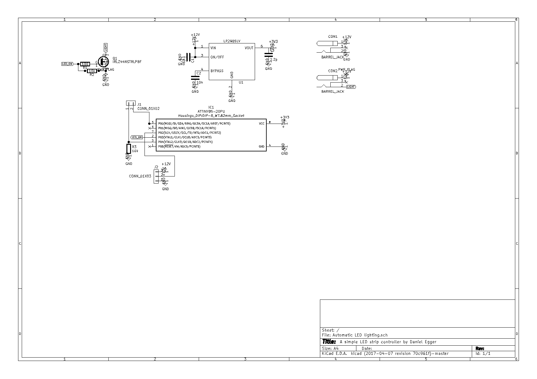
LED strip controller schematics
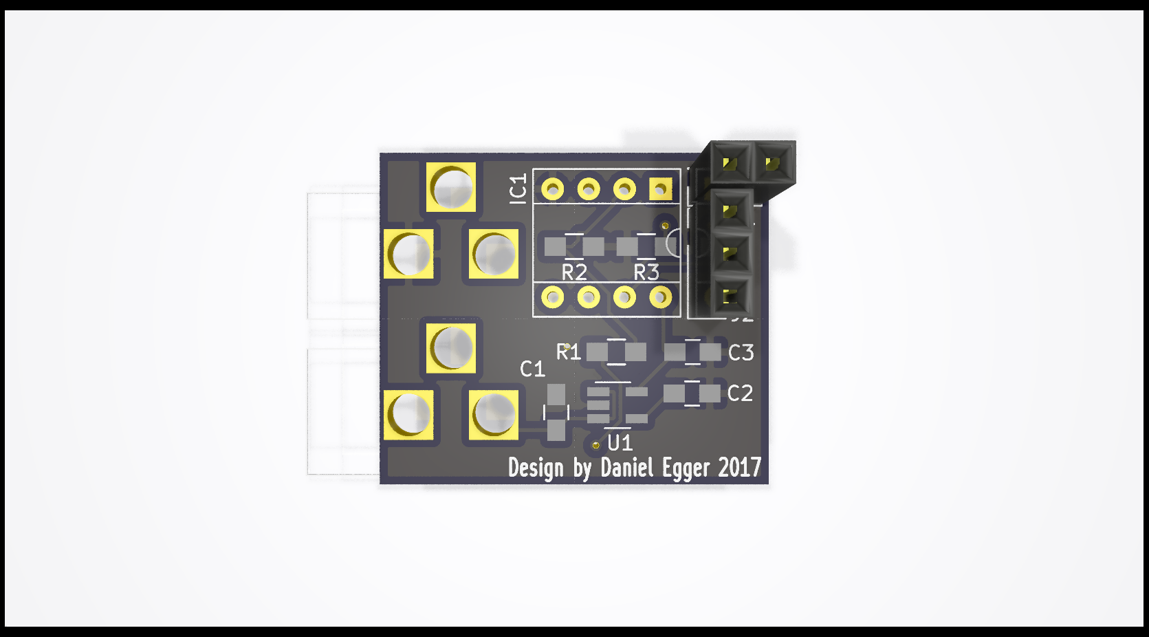
LED strip controller PCB front
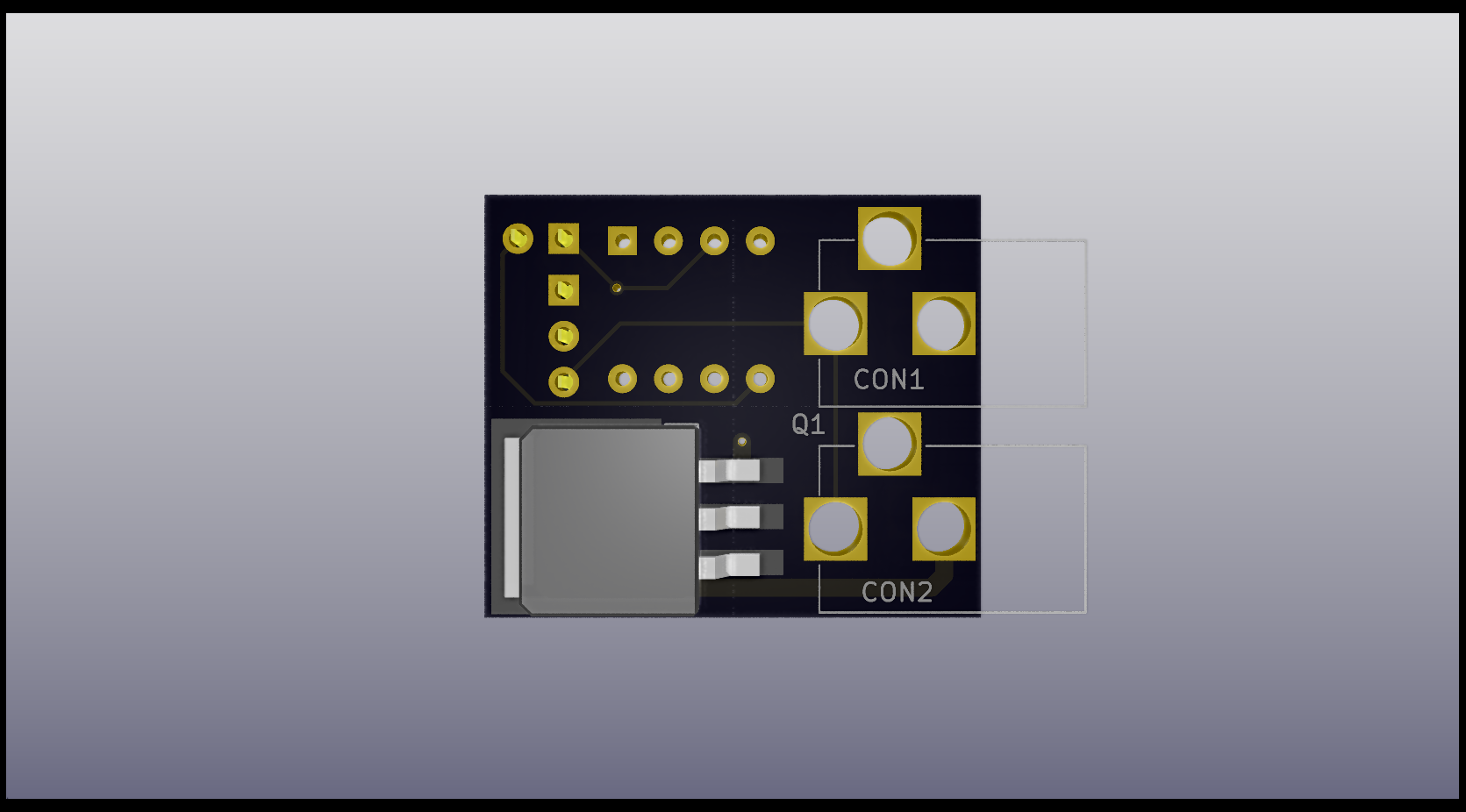
LED strip controller PCB back
(sorry, some 3D modules are not available for all components but you’ll see it in full glory later anyway ;) )
To be continued …